FAULT FINDING & MEASUREMENT
This is just to outline some basic procedures when checking a device for defects. Since there are whole books devoted to fault finding and measurement techniques, a comprehensive treatment of the matter would be well beyond the scope here.
For simplicity, "DUT" will be used as an abbreviation for Device Under Test.
Safety advice for working with high voltages:
- Always let the supply voltage decay before working on a DUT; capacitors in the supply lines may hold their charge over several minutes. You can bleed the voltage off via a resistor of sufficient wattage, and/or install an additional meter to watch the remaining voltage.
- If you have to work on a DUT with live voltage present, use one hand only and keep the other one in your pocket
FAULT FINDING
Following the points described below - in the actual order that they're given - usually leads to good results:
1. Rule out that the defect is related to anything other than the DUT itself
Check the DUT's power cable and the entire signal path (meaning, even parts further up- or downstream of the DUT) for bad connectors or cables. Distortion, reduced level or total loss of signal may well be due to issues such as bad cables or intermittent contacts of connectors or patch bays; these can be caused by oxidization of surfaces, loose solder joints, or by broken or shorted wires at the connector or inside the cable.
In case of distortion, double-check the gain staging before and after the DUT for possible headroom problems
2. Visual inspection of the DUT's outside
Are displays, lamps etc. still operational, or is there a complete loss of power?
The latter would indicate any of the following:
- bad power cable or connector
- blown fuse
- defective PSU section
3. Visual inspection of the DUT's inside
Check for obvious loose solder joints
Look for any loose metallic parts or particles (such as solder remains) flying about, sticking to the PCB, or elsewhere. Chances are they might have caused shorts.
Check if any components look unusual:
- burnt resistors
- bulged or leaky capacitors
- cracked tubes (seriously, I've once had one in an amp I got shipped, due to very poor packaging)
4. Check operating voltages
Start from the PSU and work yourself along the supply rails in the circuit
This can reveal bad components such as:
- non-functioning voltage regulators
- resistors or capacitors having gone open-circuit
- resistors having drifted in value
- shorted tantalum capacitors
- bad transistors, diodes, op-amp's or tubes
- cold solder joints that are less obvious
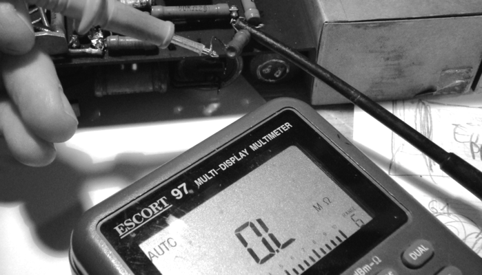
5. Trace test signal
Apply a test signal at the input and trace at which point(s) it gets lost, distorted or anything else unusual happens to it - e.g. loss of level, parasitic oscillation or intermittent signal conduct.
The deformation of different waveforms can reveal specific issues:
- A deformed sine signal will reveal gross amounts of nonlinear distortion
- A deformed square wave will reveal uneven frequency response or ringing
Generally, work you way from the more obvious problems (dead / malfunctioning power supply section, non-present supply voltages elswhere in the circuit, loose solder joints, blown or otherwise easily detectable bad parts) to the less obvious ones.
MEASUREMENT
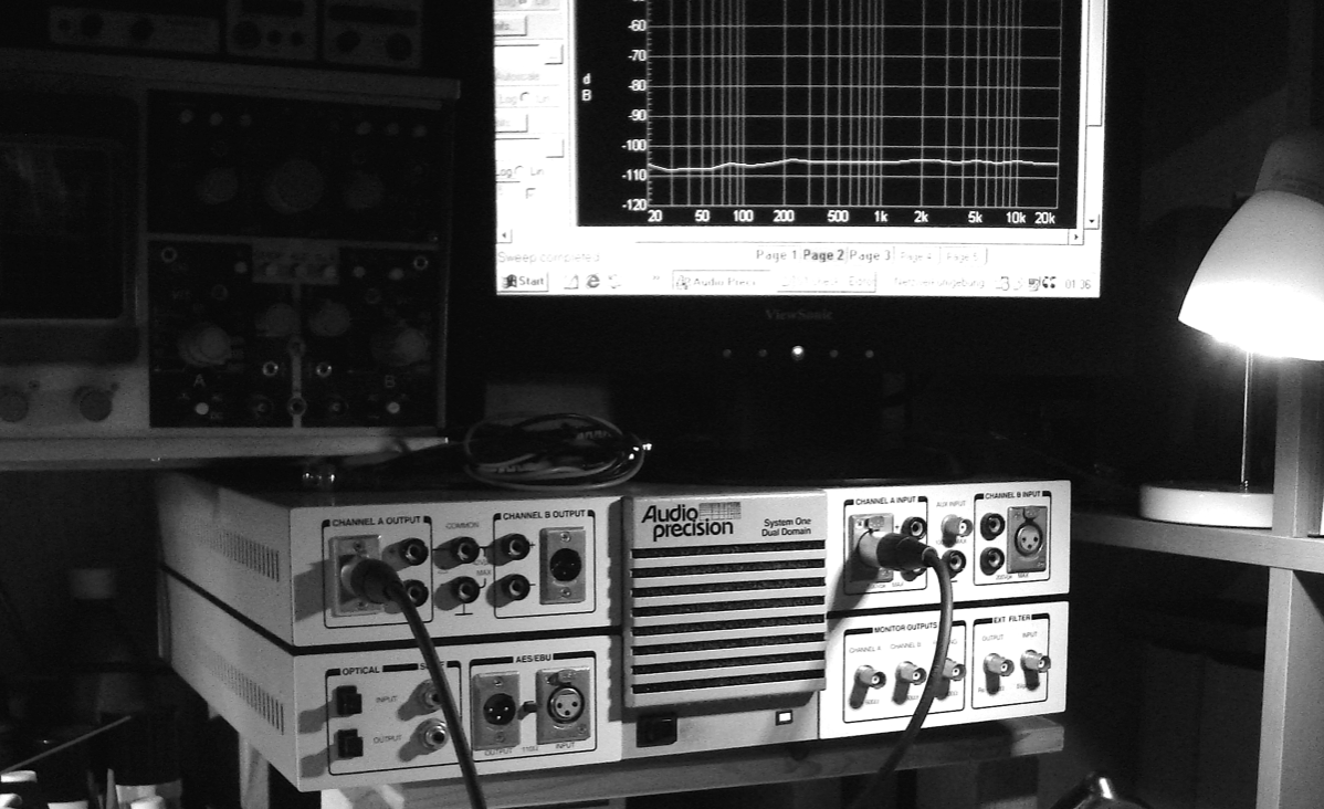
For anything more specific than the signal checks mentioned above, I go to the venerable System One by Audio Precision. Having been an industry standard for decades, it's computer interface may seem a bit outdated now, but functionality and quality of measurement still hold up today. Plus, I scored it at a very good price… ;-P
I’m running the hardware with a modern laptop and Windows 10, using the excellent APIB-USB Adapter by Udo Heusinger.
First, I usually determine the DUT's overload point by applying a sinewave and increasing the level until THD reaches 0,5%, then reduce signal by 10dB and measure Amplitude and Phase response. I also make sure to have correct loading of input and output (e.g 200 Ohms source resistance for Mic Pre's, or min. 1K load for line ("bridging") outputs.
Depending on the indication, I perform measurements such as
- Gain, Noise floor (CCIR / dBA)
- FFT, to check the noise or distortion spectrum
- THD against amplitude, to check for headroom problems
- THD against frequency, another way to assess frequency-dependent distortion
- individual harmonics against amplitude or frequency, to assess further the nature of distortion