SERVICING A V72
One of my V72's no longer puts out any signal during a recording session. I have a rack with multiple V72 modules; before going any further, I swap the unit with others to see if the fault might be related to external contact problems of wiring, patchbays etc. However, the fault travels with the unit in question as it's being swapped, so it's the V72 module itself that it's actually defective.
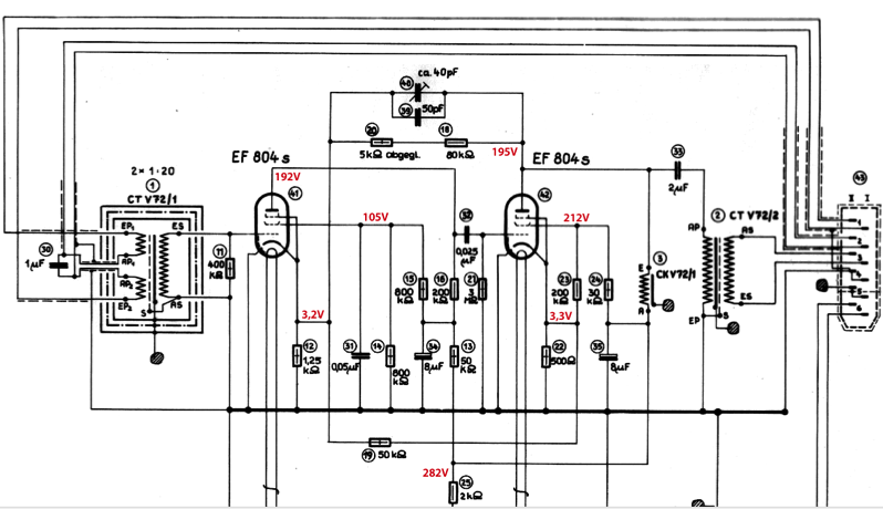
The power lamp on the module's faceplate still comes on, therefore it's not an issue of receiving power in the first place. So I dig up the schematic, slide the cover off and start checking. Since the schematic doesn't provide any reference voltages, I'm taking a second unit to compare (I have included the upper half of the schematic here, with the reference voltage fit in at the relevant points).
One of my V72's no longer puts out any signal during a recording session. I have a rack with multiple V72 modules; before going any further, I swap the unit with others to see if the fault might be related to external contact problems of wiring, patchbays etc. However, the fault travels with the unit in question as it's being swapped, so it's the V72 module itself that it's actually defective.
The power lamp on the module's faceplate still comes on, therefore it's not an issue of receiving power in the first place. So I dig up the schematic, slide the cover off and start checking. Since the schematic doesn't provide any reference voltages, I'm taking a second unit to compare (I have included the upper half of the schematic here, with the reference voltage fit in at the relevant points).
I'll first check if the PSU section is working properly and that the supply voltage gets to the anodes at all. While filament voltage is fine (6,3V), the voltages at the rectifier and the RC ripple filters seem a bit high; so does the anode voltage of the first tube (275V), while the second one is more in the ballpark. So, both tubes (I'm thinking!) must be conducting.
To see at which point the signal gets lost, I apply a sine wave to the input and trace it. In these 50+ years old units, wires are prone to break and insulation is likely to crumble away at some point, so I'm even checking the less suspicious points such as solder joints at the input connector, at transformers, tube sockets etc. The signal does pass the input transformer, goes to the input grid of the first tube, but doesn't reappear at the anode.
Might it just be a bad tube? Obviously not, because swapping out the tubes doesn't change the situation; the problem must be elswhere, so a closer check of all the voltages around the tubes is in order.
Closer Investigagion
The cathode of the first tube stage is only at 0.8V, where it's actually supposed to be at around 3V. Also, the screen grid, which should be at around 100V, doesn't give any reading on my meter, so it seems it doesn't have any voltage present. To rule out a possible defect in the first tube, I'm removing it from the socket. The contact for the screen grid still gives no reading - meaning, it's "floating" without any voltage reference, obviously rendering the tube non-coductive.
This explains why the cathode is sitting at only 0.8V; while the major portion of the regular voltage (3V) would be caused by the biasing current flowing from the first tube through R12, I'm now seeing just the portion of DC feedback from the anode of the second tube (via R18 and R20 or C39 and C40 respectively) here.
It also explains why the supply voltages of the PSU section and the first anode are high - the anode is not drawing any current, so there's no voltage drop at the anode resistor, and less voltage drop than usual across the PSU filter stages due to the reduced overall current drawn.
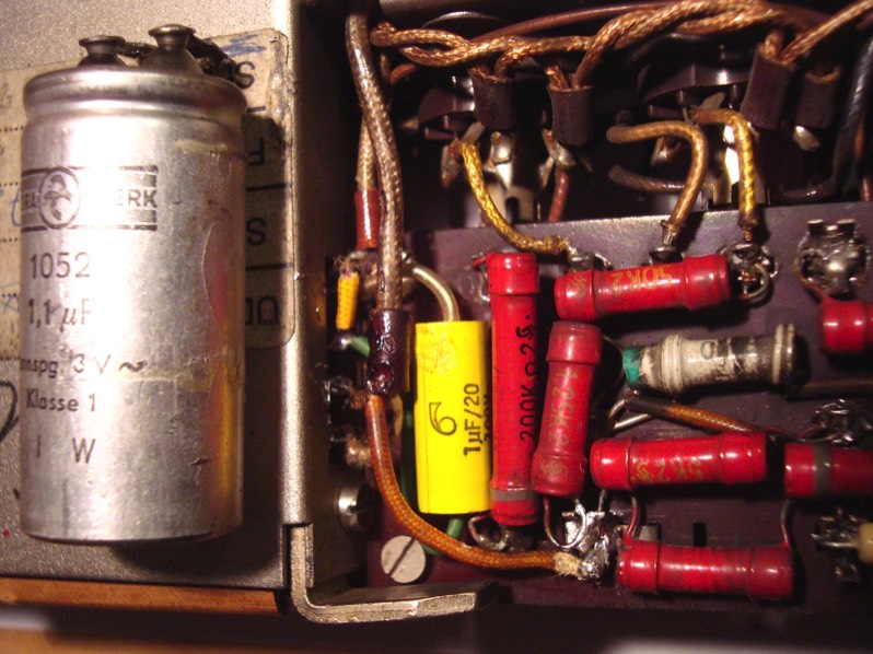
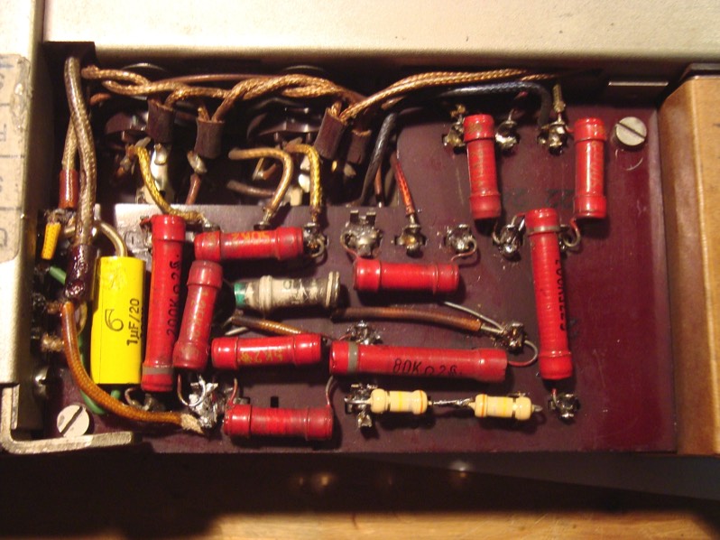
Anyway - no voltage to screen grid means that the associated capacitor or resistor is defective. I'm guessing that C31 has a short. Desoldering one leg, I'm measuring both it's capacitance and isolation resistance - they are pretty much up to spec, though, so I guessed wrong. Also R14 is pretty close to its original value.
Since I'm seeing 280V between screen resistor R15 and anode resistor R16, but no voltage between R15 and the very screen grid, the problem can only be R15 itself, then. These old carbon resistors sometimes do drift towards higher values - this one, however, has gone completely open circuit. After replacing the original 800K with 2x 390K (exact value is non critical here), the screen voltage goes back to normal. With the tube back in, the signal goes all the way through to the output. So far, so good.
Grounding Scheme
Normally, the input transformer's protective metal can is directly tied to chassis ground via one of it's screws. With this unit, I'm noticing that it the grounding scheme has been converted to V77 topology (close sibling of V72): Because the V77 has around double the gain, minimum noise floor at the input becomes more important, which obviously is achieved by tying the can to 0V potential instead. This is done using an insulating washer and a screw coated with insulation material (so chassis contact is avoided) the head of which is connected to 0V via a blue lead going to the backside of the resistor board, there connecting to the "cold" end of the input transformer's secondary (which, in turn, is connected to 0V potential through the ground pin of the first tube)
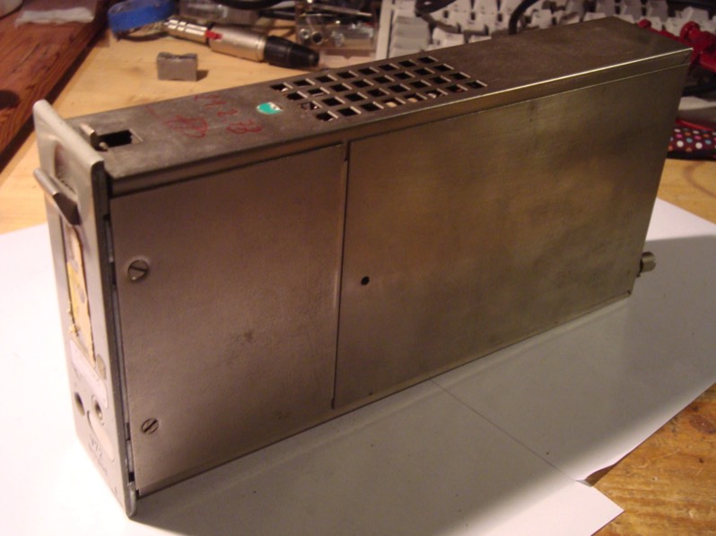
Pulling out the screw in question, it looks to be corroded, though - so despite the fact that all seems well for the time being, I'd rather check for anything else unusual while I'm at it. Sadly, in order to access the input transformer, I'll have to disassemble the whole transformer/inductor section, which is located between the metal sheets at the front of the module. But actually, I've always wanted to see how it looks in there ;-P
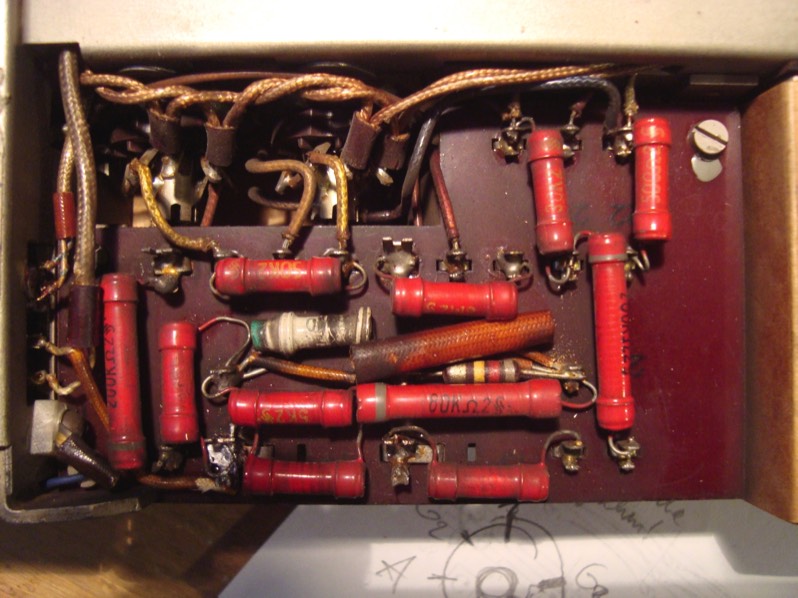
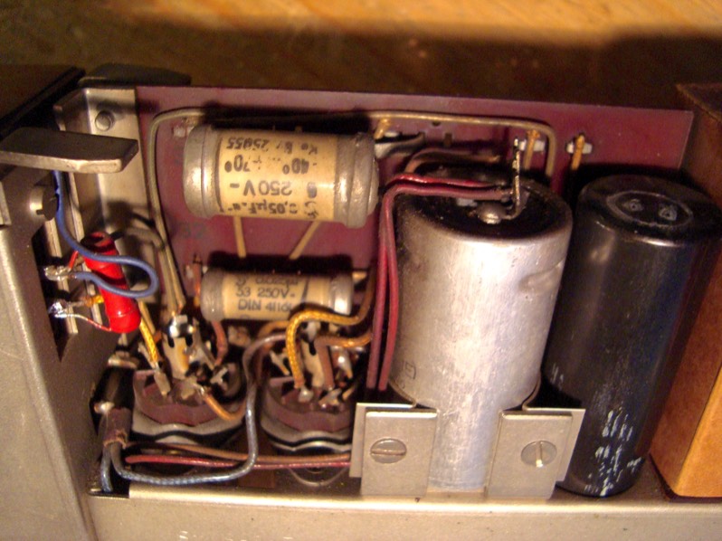
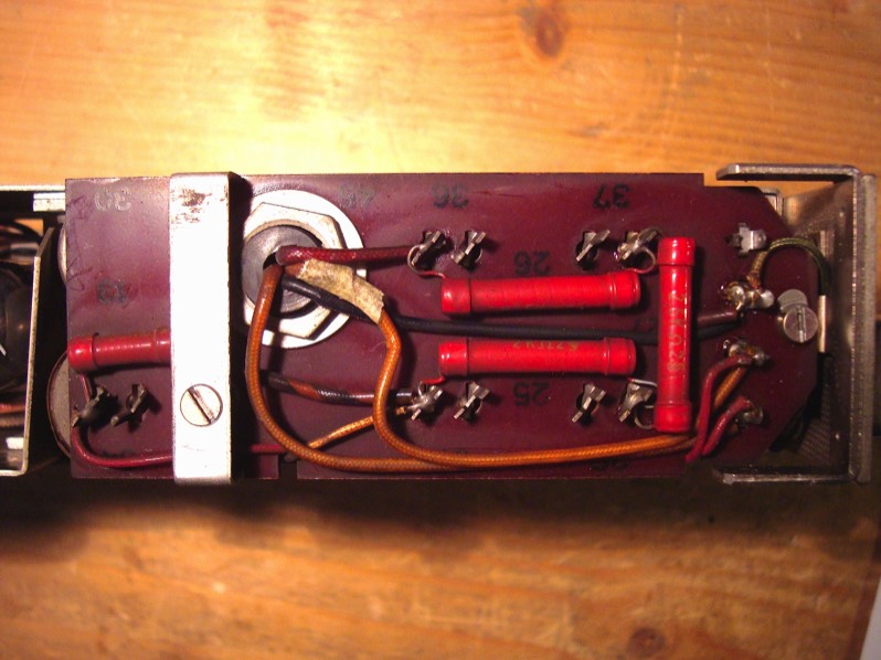
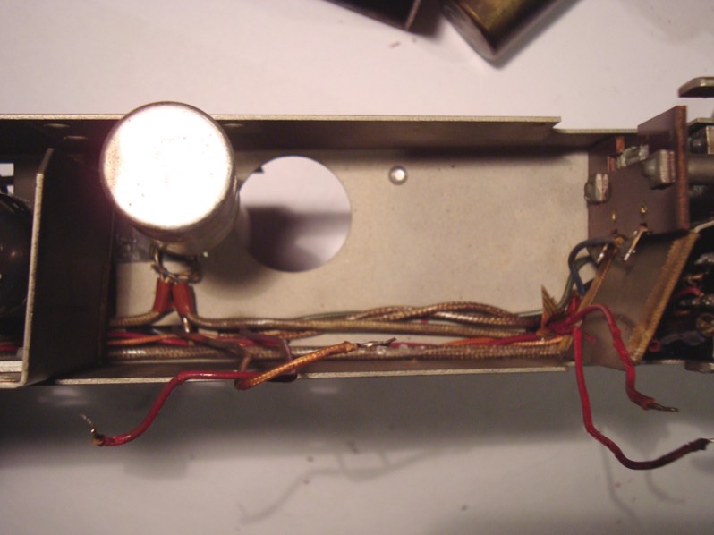
For detailed pictures of the innards (of the whole unit, actually), see the Dissection section.
I ended up not finding anything unusual - so, having verified that the corroded-looking screw makes electrical contact nicely, I'm reassembling everything. I'm also reverting the grounding scheme back to V72 default.
Sadly, we're not quite done yet... - while desoldering, I realized that the middle taps of the input transformer's primary windings are connected by a solder bridge, bypassing C30 which constitutes the low cut. By factory default, both ends of the capacitor are also fed to the rear connector at pins 2 a/b, to make provision for switching off the low cut off externally. I'm removing the solder bridge since I actually use this very filter switching arrangement in my rack.
Restoring the High Pass Filter
With the solder bridge removed, the output drops considerably in level. My first guess is that the very reason for bypassing that capacitor C30 was that it had lost most of its actual capacitance, pushing the 40Hz cutoff frequency considerably upwards. Increasing the frequency of the test signal brings the level back to where it should be, so I guessed right. To complicate matters, the capacitor isn't located anywhere close to the input transformer physically - because of it's size, it sits halfway between the transformer and the rear connector, right next to the other big capacitors from the PSU section. This entire section is what I have to remove just to get to the one capacitor in question! No wonder that the former owner couldn't be bothered to change it, and thus chose to bypass it altogether...
After more desoldering and unscrewing, I can access the capacitor, which indeed measures just 1/10 of it's original value (0.1µF instead of 1µF), resulting in an upward shift of the cutoff frequency from 40 to around 400Hz. The replacement I'm installing is a more modern MKT type much smaller in size, so I'll attach it to the input transformer directly and fit it right onto the neighbouring circuit board. I'm leaving the wiring to the rear connector in place so external bypassing can still be done.
Summary:
- restored signal flow in the first tube stage by replacing screen grid resistor
- restored high pass cutoff frequency by replacing capacitor at the i/p transformer's primary
- reinstalled provision for remote-switching of high pass
- reverted grounding scheme back to factory default